Sketch and board connections
Release notes
Sketch version 11.30 release notes - Dec – 2021
- Code fixed (more stable)
- Added new sensors: BMP280, SHT21
- ESP8266: compatible with core 3.02 library (more stable)
- Mega: added watchdog
Previous Sketch release notes
Sketch version 11.20 release notes – April – 2021
- New more flexible timer implementation: start time, stop time, more robust then the previous version.
- OTA for NodeMCU/ESP8266: one 11.20 is installed, the next sketches can be installed using OTA (On The Air)
- Sleep mode for ESP8266: enabling the SLEEP mode the board can send its sensor every 10 minutes to the server. Power consumption is very low, batteries can be used.
- ESP8266: DHCP has been fixed
- STM32: interrupt fix
Sketch version 11 release notes – March 29th – 2020
- Updated STM32 sketch for the new STM core library
- NodeMCU/ESP8266: updated Andruino WiFi Manager library for the new ESP core library.
- Sensors:
- Added Bosch I2C Temperature and pressure sensor: BMP085/180
- Updated Dallas temperature sensor: more than one sensor on the same bus
Sketch version 10.3 release notes – March 20th – 2019
- Inverted pin: when the device is reset, the initial state of the PIN will be float, so if there are connected relays, they will not toggle.
- Various improvements on stability.
- Improved startup time when in wifi shield configuration.
- PIN10 deleted from the PIN list (it is used by ethernet shield as CS).
- Led blink option also on ESP8266 wifi shield option
- Sketch NO configurations (sketch senza configurazioni)
- All the user configurations (email, pin, board name, wifi ssid, etc) will be not yet written on the sketch.
- Le configurazioni utente (email, pin, board name, wifi ssid, etc) non verranno più scritte nello sketch.
- Web page configurations (configurazione tramite pagina web)
- Using a web page, the user will insert his account informations (email, pin, board name). For the next sketch updates, is not yet necessary to insert them again because these informations are stored on device flash.
- Utilizzando un’interfaccia web, l’utente immetterà la propria email, pin e nome board. Per i successivi aggiornamenti, lo sketch sarà già configurato poiché queste informazioni sono memorizzate nella memoria flash della board usata.
- Fix from v9.51: (Jan 2018)
- Timer fix: timer #0 did’t work and reset PIN 10 at 00:00.
Delete all the previous libraries and install the new one
Install instructions
How upload the sketch on your board
Using the sketch named: ANDRUINO_IOT_SKETCH you can configure a lot of Arduino boards connected to internet (IoT Nodes). Using AndruinoApp, you can control and monitor all the relays and sensors running on the different boards.
- Download the official Arduino IDE. External link
- Download my latest release of Andruino sketch – Below sections
- Using the #define options you can enable the different sensors and/or different Arduino board (below, I have already created different .zip file for different boards)
- Compile and upload on the board
(see below instruction for each board)
Sketch configuration files: PINS and SENSOR
-
A_SET_CONFIG.ino: used to select the right shield or the sensor libraries
-
B_SET_NETWORK.ino: configure the SERVER/DIRECT mode (above list)
-
C_SET_PIN.ino: choose the PIN used as INPUT and OUTPUT. Select the inversion is is needed
Sketch download sections
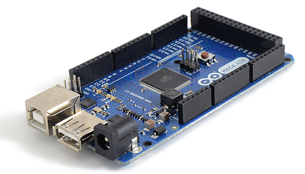
Arduino Mega 2560 + Cable Ethernet shield
Download sketch for ethernet W5100
Version configured for Arduino Mega 2560 and Ethernet shield W5100
Compiler option used:
#define ETHERNET_SHIELD 1
Download sketch for ethernet W5200
Version configured for Arduino Mega 2560 and Ethernet shield W5200
Compiler option used:
#define ETHERNET_SHIELD_V2 1
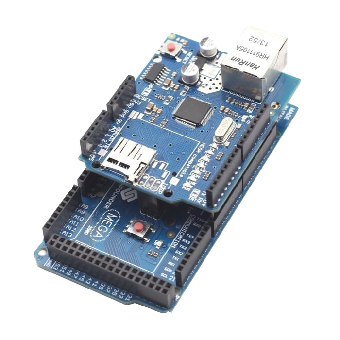
Main board connections with ethernet module
Plug Arduino Mega to ethernet shield and the cable to the router.
Video guide - compile and upload
Video guide - Ethernet web page configuration: user and PIN
Arduino Mega 2560 + WiFi ESP8266
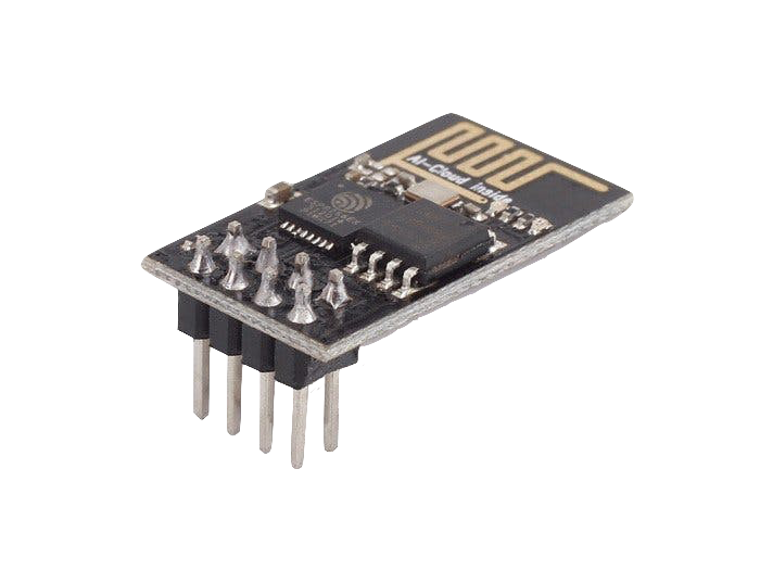
Download sketch for WiFi connection (ESP8266 module)
Version configured for Arduino Mega 2560 and WiFi module ESP8266
Compiler option used:
#define WIFI_ESP8266_SHIELD 1
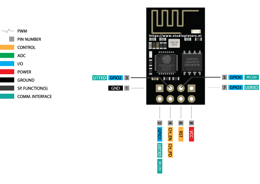
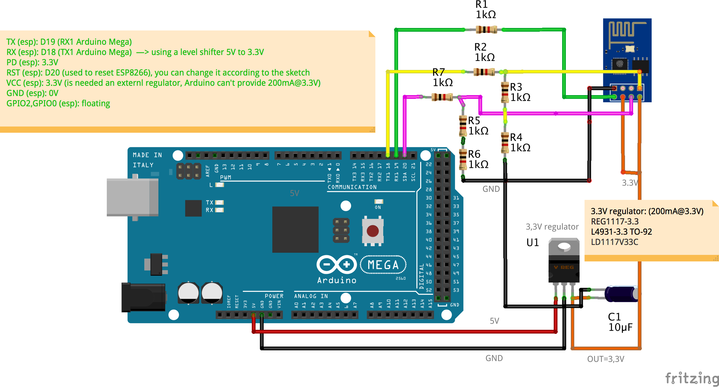
Main board connections with WiFi module
ESP8266 vs Arduino PINS:
- TX (esp): D19 (RX1 Arduino Mega)
- RX (esp): D18 (TX1 Arduino Mega) —> using a level shifter 5V to 3.3V
- PD (esp): 3.3V
- RST (esp): D20 (used to reset ESP8266), you can change it according to the sketch, find: ESP8266_RESET_PIN
- VCC (esp): 3.3V (since that are needed 200mA, an external regulator is mandatory)
- GND (esp): 0V
- GPIO2,GPIO0 (esp): floating
NOTE: suggested max wires lenght is 10-15 cm
WARNING: ESP8266 works at 3.3V, so don’t connect it directly to Arduino Mega. Use the below schematic or use the below 5V to 3.3V adapter.
TIP:
To avoid external components, can be used a Breadboard Adapter Level Converter 3.3V- 5V: link
Using this adapter, the wires can be connected directly from Arduino Mega to it.

Video guide - compile and upload
Video guide - WiFi web page configuration: Wifi router, user and PIN
Node MCU – Embedded WiFi
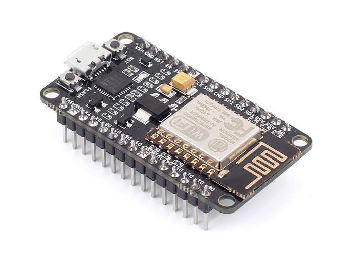
Download sketch for Node Mcu
Version configured for NodeMCU
ESP8266 Arduino install: Enter http://arduino.esp8266.com/stable/package_esp8266com_index.json into the “Additional Boards Manager URLs” field as shown in the figure below. Then, click the “OK” button
Compiler option used:
#define NODE_MCU
Upload sketch and board connections
Simply connect the USB cable and upload the sketch.
Video guide - compile and upload
Video guide - web page configuration: WiFi router, user and PIN
Wemos D1 – Embedded WiFi

Download sketch for Wemos D1
Version configured for Wemos D1
ESP8266 Arduino install: Enter http://arduino.esp8266.com/stable/package_esp8266com_index.json into the “Additional Boards Manager URLs” field as shown in the figure below. Then, click the “OK” button
Compiler option used:
#define WEMOS_D1_MINI
Upload sketch and board connections
Simply connect the USB cable and upload the sketch.
Video guide - compile and upload
Video guide - web page configuration: WiFi router, user and PIN
ESP8266/ESP01 – Embedded WiFi
Download sketch for ESP8266 - ESP01
Version configured for ESP8266 ESP01
Compiler option used:
#define ESP8266_01_GENERIC 1
Compiler option: Generic ESP8266, configure flash 512K: fs: 32, ota: 230
ESP8266 Arduino install: Enter http://arduino.esp8266.com/stable/package_esp8266com_index.json into the “Additional Boards Manager URLs” field as shown in the figure below. Then, click the “OK” button
Download sketch for ESP8266 - ESP12E - 512KB Flash
Version configured for ESP12E
Compiler option used:
#define ESP8266_12E_CONF2 1
Compiler option: Generic ESP8266, configure flash 512K: fs: 32, ota: 230
ESP8266 Arduino install: Enter http://arduino.esp8266.com/stable/package_esp8266com_index.json into the “Additional Boards Manager URLs” field as shown in the figure below. Then, click the “OK” button
Upload sketch and board connections
Use FTDI 3.3V USB to RS232 converter
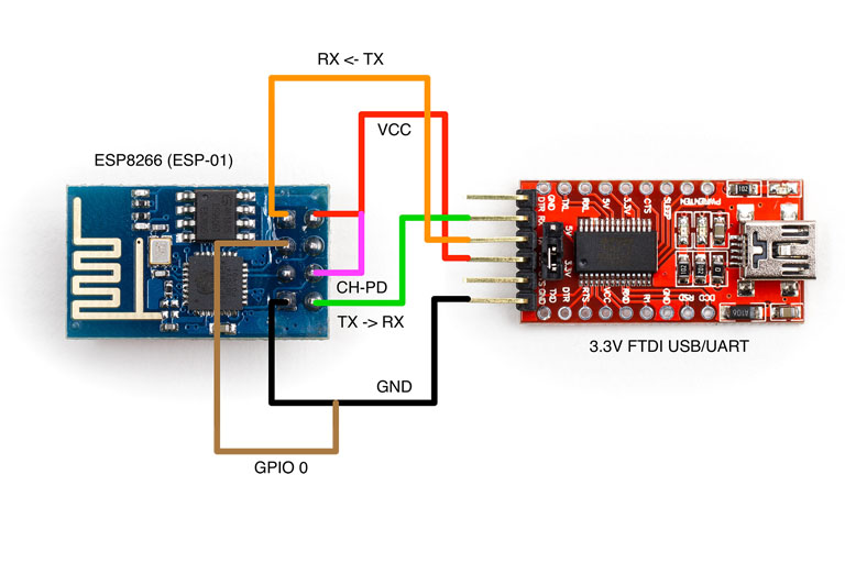
Connection to program sketch:
ESP8266:————– >FTDI:
GND ————————– GND
GPIO-2 ———————– Not connected (open)
GPIO-0 ———————– GND
RXD (GPIO-3) ————— RX
TXD (GPIO-1) ————— TX
CH_PD ———————- 3.3V
RST ————————— (Read Below Instruction)
VCC ————————– 3.3V
Very Important Instruction:
- Now before hitting upload, take GPIO-0 to ground.
- And RST to ground afterwards, remove RST after half a second (the blue LED flashes for some millisecond).
- Hit upload, the blue flashes once and then blinks till it gets uploaded
Connections after programming:
ESP8266:————– >FTDI (to use serial monitor)
GND ——————– GND
GPIO-2 —————– Not connected (open)
GPIO-0 —————– Not connected (open)
RXD (GPIO-3) ——– RX
TXD (GPIO-1) ——— TX
CHPD —————— 3.3V
RST ——————– Not connected (open)
VCC ——————– 3.3V
Video guide - compile and upload
Video guide - web page configuration: WiFi router, user and PIN
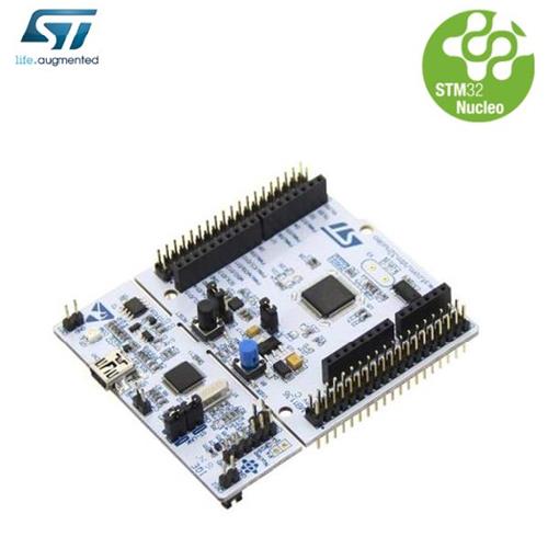
Nucleo STM32 + WiFi ESP8266
Download sketch for WiFi connection (ESP8266 module)
Version configured for Nucleo STM32 and WiFi module ESP8266
Compiler option used:
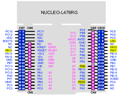
#define STM32_NUCLEO_64 1 //tested on Nucleo 64 pin L476RG
or
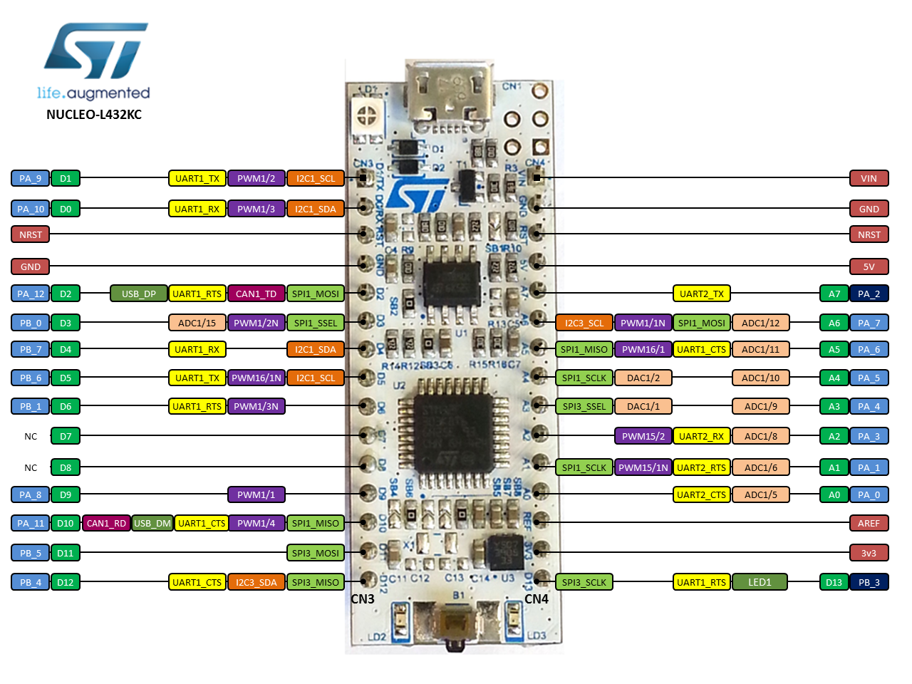
#define STM32_NUCLEO_32 1 //tested on Nucleo 32 pin L432KC
Main board connections with WiFi module
STM32 Nucleo board 64 PIN connection with WiFi module:
- TX (GPIO1 esp): D2 (PA10 RX Nucleo)
- RX (GPIO3 esp): D8 (PA9 TX Nucleo)
- PD (CH_PD esp): 3.3V Nucleo
- RST (RST esp): D7 (PA8 Nucleo), you can change it according to the sketch, find: ESP8266_RESET_PIN
- VCC (esp):3.3V Nucleo
- GND (esp): gnd Nucleo
STM32 Nucleo board 32 PIN connection with WiFi module:
- TX (GPIO1 esp): D0 (PA10 RX Nucleo)
- RX (GPIO3 esp): D1 (PA9 TX Nucleo)
- PD (CH_PD esp): 3.3V Nucleo
- RST (RST esp): D3 (PB0 Nucleo), you can change it according to the sketch, find: ESP8266_RESET_PIN
- VCC (esp):3.3V Nucleo
- GND (esp): gnd Nucleo
GPIO2,GPIO0 (esp): floating
NOTE: suggested max wires lenght is 10-15 cm
NOTE: Nucleo board works at 3.3V, so it is compatible with ESP8266 and so no level shifter is required.
Nucleo 64 pin:
Nucleo 32 pin:
Video guide - compile and upload
Video guide - web page configuration: WiFi router, user and PIN
SonOff – Embedded WiFi (based on ESP8266)

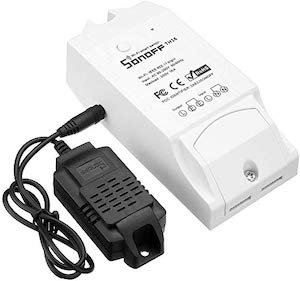

Download sketch for SonOff
Version configured for SonOff
Compiler options used:
#define SONOFF_BASIC 1
or
#define SONOFF_S20 1
or
#define SONOFF_TH10 1
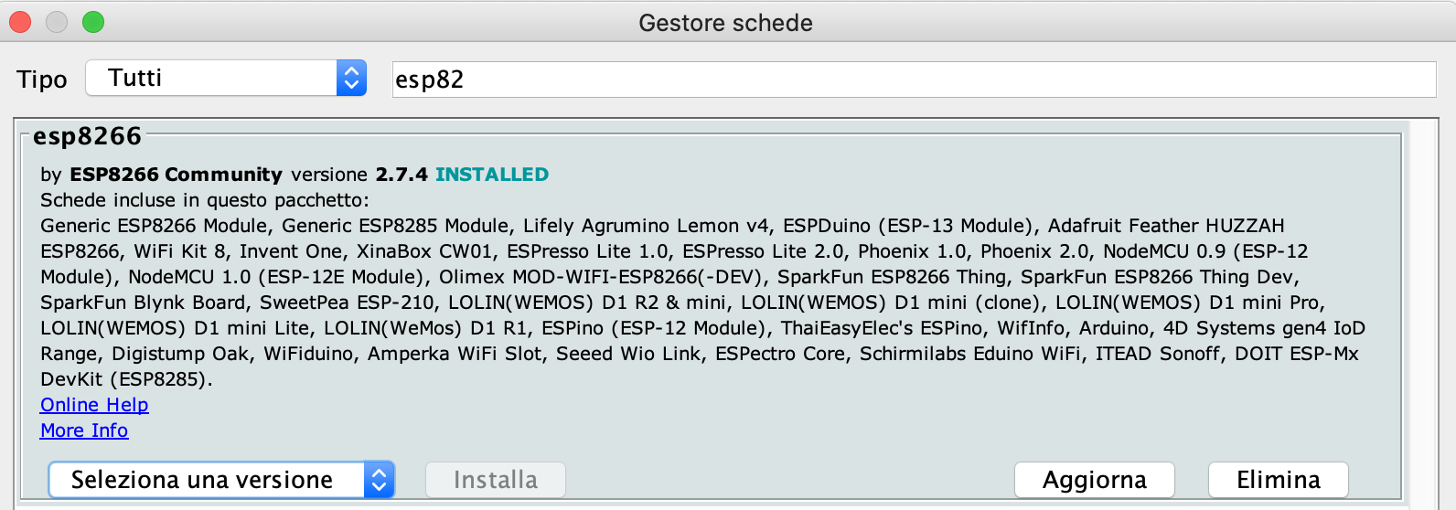
IMPORTANT: esp8266 core version has to be 2.7.4 (not version 3)
Main board connections
Arduino Mega and ethernet are simply connected using shield connector.
Video guide - compile and upload
Compiler options:
- Board: Generic ESP8266 Module
- Option: DOUT option enabled
Video guide - web page configuration: WiFi router, user and PIN
Andruino Winner during Arduino-Day 2019
Andruino Project has been selected by a panel of experts as the winner of the HOME AUTOMATION category in the Arduino Day Community Challenge

Andrea Scavuzzo