Sensors and Actuators
Sensors
Ultrasonic Module
Temperature and Humidity
AC Energy Meter
IR infrared
Soil Hygrometer
Digital Barometric Pressure
Photoresistor
Sensor Module Smoke
Motion Sensor Module Vibration Switch Alarm
Humidity and Rain Detection
Accelerometer Module
Actuators
Relays
Lights
Motor control
Domestic appliances
Servo
electric door lock
Sensors
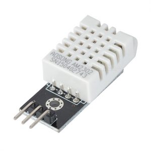
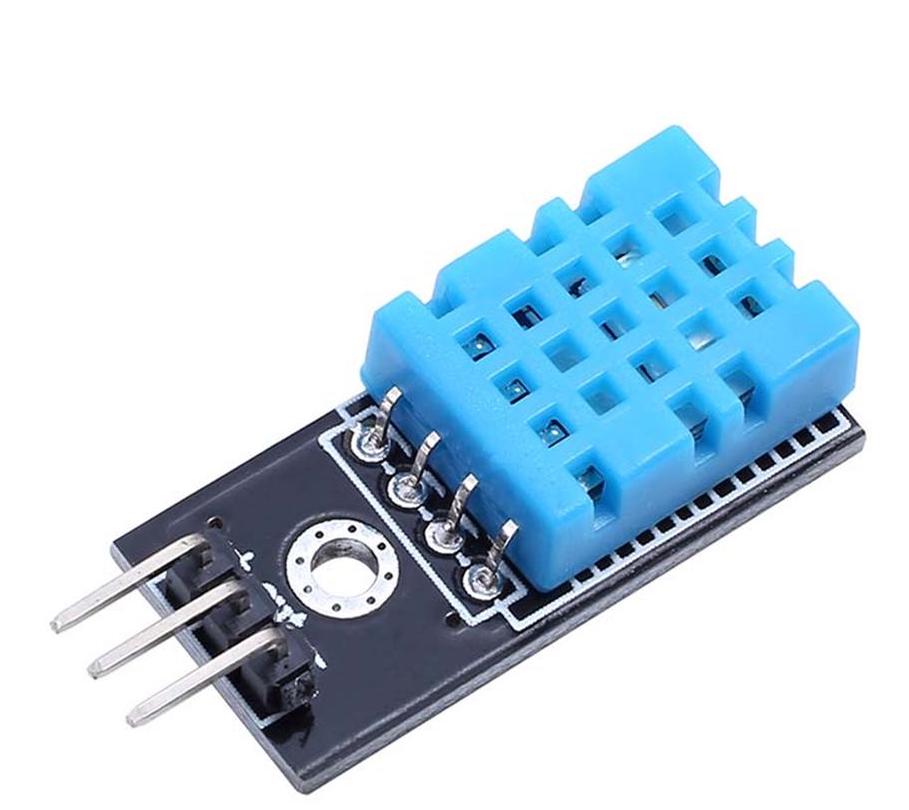
Temperature sensor – Adafruit DHT22/11
Characteristics
The DHT11 and DHT22 sensors are used to measure temperature and relative humidity. These are very popular among makers and electronics hobbyists. These sensors contain a chip that does analog to digital conversion and spit out a digital signal with the temperature and humidity. This makes them very easy to use with any microcontroller.
The DHT11 and DHT22 are very similar, but differ in their specifications.
The DHT22 sensor has a better resolution and a wider temperature and humidity measurement range. However, it is a bit more expensive, and you can only request readings with 2 seconds interval.
The DHT11 has a smaller range and it’s less accurate. However, you can request sensor readings every second. It’s also a bit cheaper.
Despite their differences, they work in a similar way, and you can use the same code to read temperature and humidity. You just need to select in the code the sensor type you’re using.
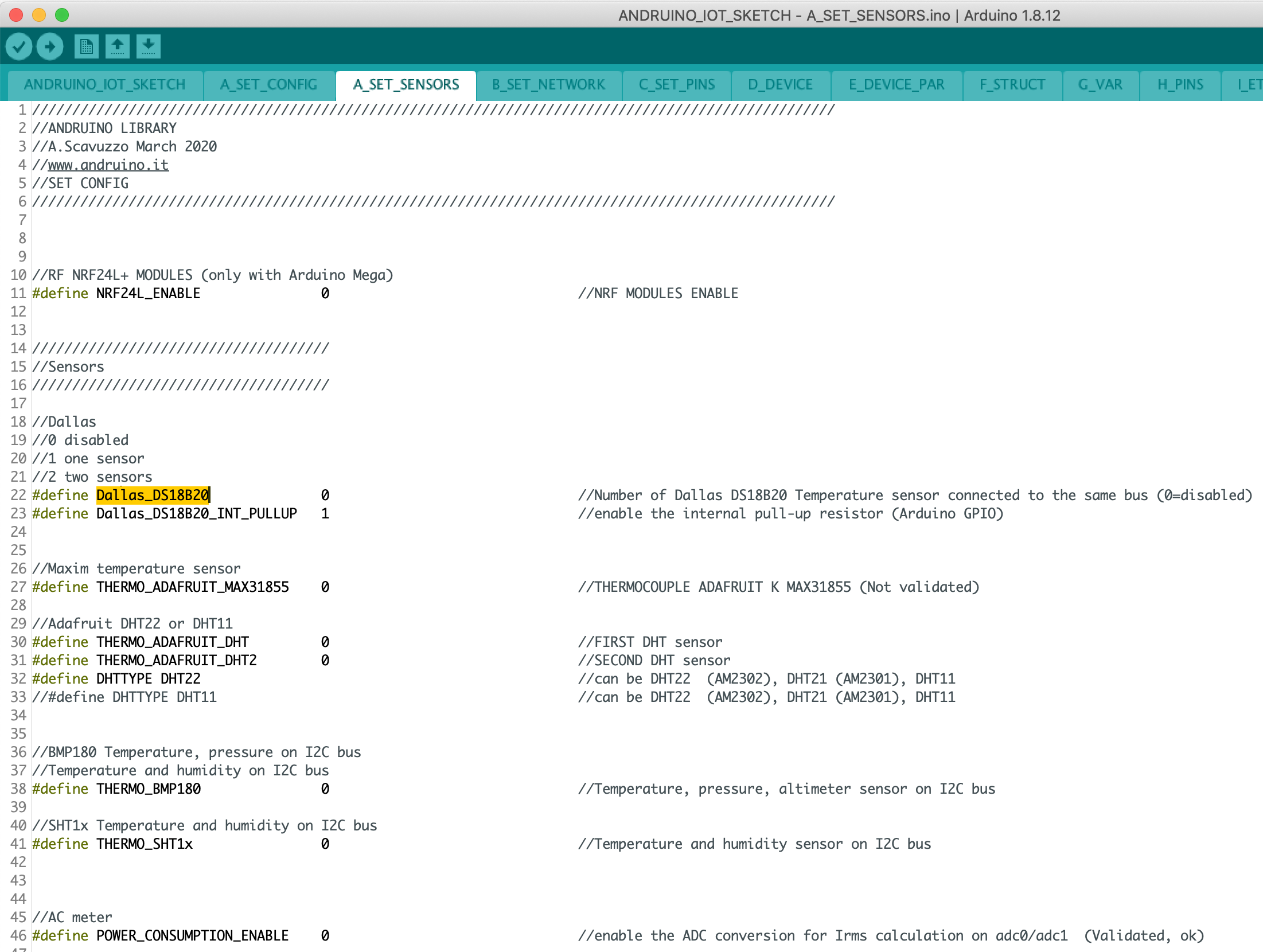
Sketch compiler defines
Compiler option used:
Library enabler:
#define THERMO_ADAFRUIT_DHT 0 (DISABLE)
#define THERMO_ADAFRUIT_DHT 1 (ENABLE)
Type selection:
#define DHTTYPE DHT22
#define DHTTYPE DHT11
PIN definition:
#define DHT_PIN 2
#define DHT2_PIN 9 (second DHT)
App Variable assignment:
#define VIRTUAL_VAR_INDEX_HUM_DHT 0
#define VIRTUAL_VAR_INDEX_TEMP_DHT 1
#define VIRTUAL_VAR_INDEX_HUM_DHT2 5 (second DHT)
#define VIRTUAL_VAR_INDEX_TEMP_DHT2 6 (second DHT)
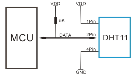
Schematic connections

How to display it on AndruinoApp
From Andruino App, select board name and variable number:
- Humidity: variable number 0
- Temperature: variable number 1
Temperature sensor – Dallas DS18B20
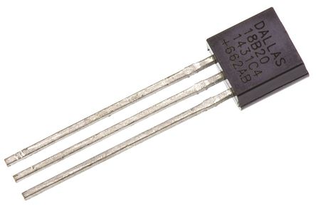
Characteristics
DS18B20 Sensor Specifications
- Programmable Digital Temperature Sensor
- Communicates using 1-Wire method
- Operating voltage: 3V to 5V
- Temperature Range: -55°C to +125°C
- Accuracy: ±0.5°C
- Output Resolution: 9-bit to 12-bit (programmable)
- Unique 64-bit address enables multiplexing
- Conversion time: 750ms at 12-bit
- Programmable alarm options
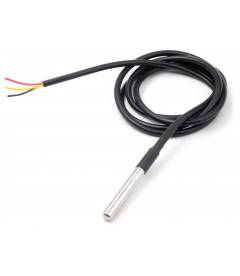
The DS18B20 is a 1-wire programmable Temperature sensor from maxim integrated. It is widely used to measure temperature in hard environments like in chemical solutions, mines or soil etc. The constriction of the sensor is rugged and also can be purchased with a waterproof option making the mounting process easy. It can measure a wide range of temperature from -55°C to +125° with a decent accuracy of ±5°C. Each sensor has a unique address and requires only one pin of the MCU to transfer data so it a very good choice for measuring temperature at multiple points without compromising much of your digital pins on the microcontroller.
How to use the DS18B20 Sensor
The sensor works with the method of 1-Wire communication. It requires only the data pin connected to the microcontroller with a pull up resistor and the other two pins are used for power as shown below.
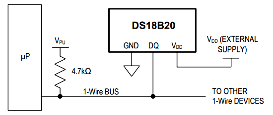
The pull-up resistor is used to keep the line in high state when the bus is not in use. The temperature value measured by the sensor will be stored in a 2-byte register inside the sensor. This data can be read by the using the 1- wire method by sending in a sequence of data.
Sketch compiler defines
Library enabler:
#define Dallas_DS18B20 0 (DISABLE)
#define Dallas_DS18B20 1 (ENABLE one sensor)
#define Dallas_DS18B20 2 (ENABLE two sensors)
(you can put different sensors on same bus)
Type selection:
only one type
PIN definition:
#define ONE_WIRE_BUS 5
PIN configuration:
#define Dallas_DS18B20_INT_PULLUP 1 (Enable internal pull-up)
App Variable assignment:
#define VIRTUAL_VAR_INDEX_TEMP_DS18B20 7
Schematic connections
Arduino PINS:
- PIN5 (digital data line). Can be changed modifying the#define ONE_WIRE_BUS
- VDD (5V or 3.3V), GND
- Pullup resistor (4,7 Kohm)
AndruinoApp sensor:
- add a new sensor (DS18B20)
- select variable 7 (var 8 for other DS18B220 on the same line)

How to display it on AndruinoApp
From Andruino App, select board name and variable number:
- Temperature: variable number 7
- If more sensors: variable 8,9,10…
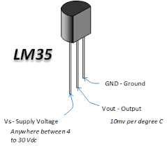
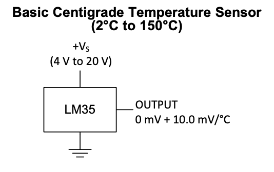
Generic analog sensor connected to analog ADC input – TMP35 Temperature
Characteristics
LM35 Sensor Specifications
- Calibrated Directly in Celsius (Centigrade)
- Linear + 10-mV/°C Scale Factor
- 0.5°C Ensured Accuracy (at 25°C)
- Rated for Full −55°C to 150°C Range
- Suitable for Remote Applications
- Low-Cost Due to Wafer-Level Trimming
- Operates From 4 V to 30 V
- Less Than 60-μA Current Drain
- Low Self-Heating, 0.08°C in Still Air
- Non-Linearity Only ±¼°C Typical
- Low-Impedance Output, 0.1 Ω for 1-mA Load
Description
The LM35 series are precision integrated-circuit temperature devices with an output voltage linearlyproportional to the Centigrade temperature. The LM35 device has an advantage over linear temperature sensors calibrated in Kelvin, as the user is not required to subtract a large constant voltage from the output to obtain convenient Centigrade scaling. The LM35 device does not require any external calibration or trimming to provide typical accuracies of ±¼°C at room temperature and ±¾°C over a full −55°C to 150°C temperature range. Lower cost is assured by trimming and calibration at the wafer level. The low-output impedance, linear output, and precise inherent calibration of the LM35 device makes interfacing to readout or control circuitry especially easy. The device is used with single power supplies, or with plus and minus supplies. As the LM35 device draws only 60 μA from the supply, it has very low self-heating of less than 0.1°C in still air. The LM35 device is rated to operate over a −55°C to 150°C temperature range, while the LM35C device is rated for a −40°C to 110°C range (−10° with improved accuracy).
How to use the LM35 Sensor
The pull-up resistor is used to keep the line in high state when the bus is not in use. The temperature value measured by the sensor will be stored in a 2-byte register inside the sensor. This data can be read by the using the 1- wire method by sending in a sequence of data.
Sketch compiler defines
Library enabler:
no #define
PIN definition:
You can connect the output of the analog signal to any of the Arduino Analog input (ex: A0)
PIN configuration:
no #define
App Variable assignment:
No variable used. The value will be selected using analog (ex: A0)
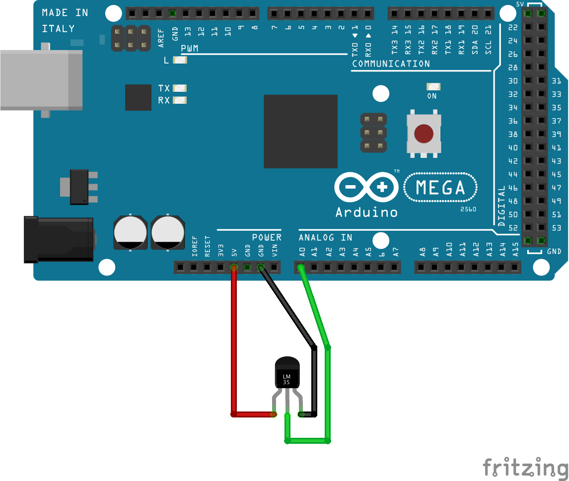
Schematic connections
Arduino PINS:
- You can connect it to Analog 0 (A0)
AndruinoApp sensor:
- add a new sensor (LM35)
- select board name and then analog 0
How to display it on AndruinoApp
From Andruino App, select board name and variable number:
- Temperature: variable number 7
- If more sensors: variable 8,9,10…
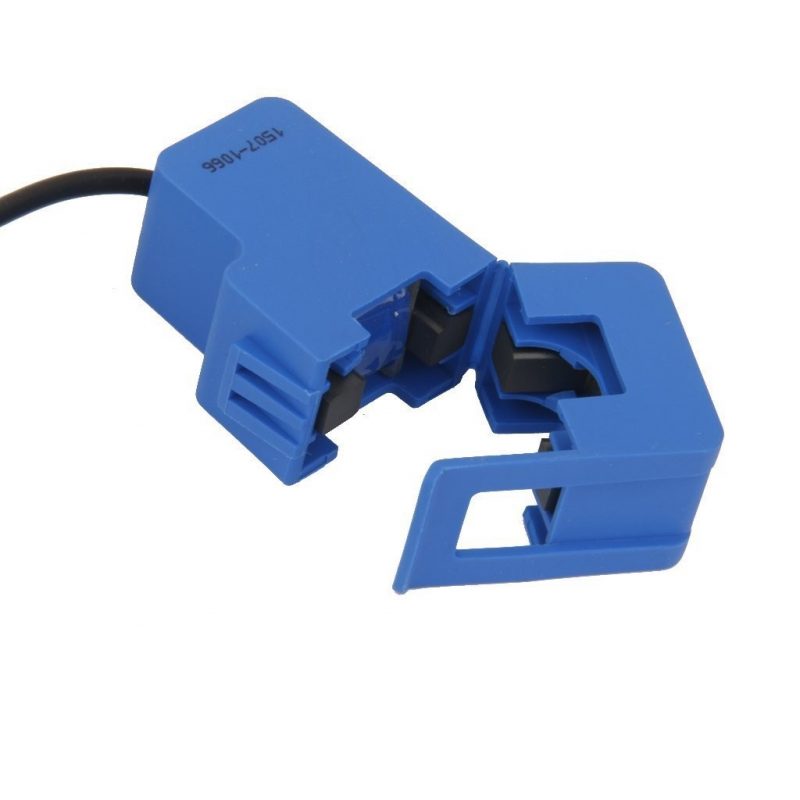
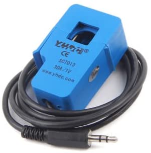
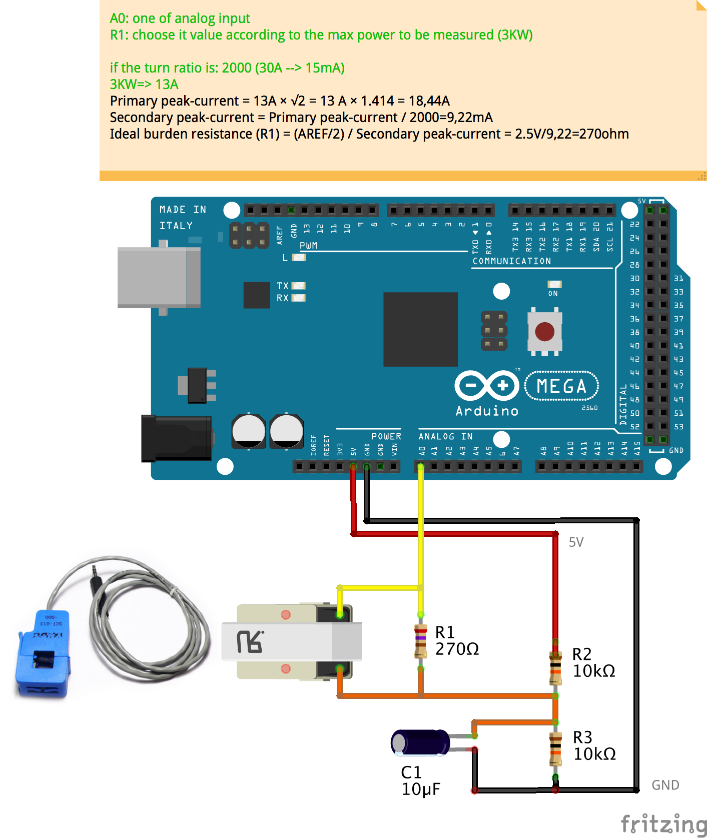
AC Energy Meter
Characteristics
Non-invasive AC Current Sensors are a good way to measure real consumption without altering the electrical composition of the elements to be analyzed. They work by magnetic induction, so that the field generated in the cable, used to power the device, induces a current in the transformer integrated in the sensor. In this way we can know what the current is in the power cable and therefore the actual consumption of the device to be measured.
Among the variety of sensors that are in the SCT-013 series we will use the STC-013-000 model because it is the only one that does not have an integrated resistance, allowing us to adjust the measuring range in which we work, as well as you can see in the table can measure currents up to 100A.
Sketch compiler defines
Library enabler:
#define POWER_CONSUMPTION_ENABLE 1
(by default enable two power sensors)
PIN definition (ADC input used):
#define IRMS0_ADC_CH 0
#define IRMS1_ADC_CH 1
Resistor selection (ohm):
#define IRMS0_RSENSE 330
#define IRMS1_RSENSE 330
App Variable assignment:
Channel 0: VAR5
Channel 1: VAR6
Schematic connections
To connect to Arduino we have to use a very simple circuit, in which the values of its components will determine the measurement range. The Arduino itself also will impose limitations such as the maximum value of the input voltage in the digital analog converter and the number of bits (10 bits) which will have a resolution limited.
Being an AC measurement to do it with Arduino we have to create a virtual ground by a voltage divider because we can measure only positive values, so that the intermediate value is 2.5V. This causes the maximum amplitude of the voltage is 2.5V.
To assign the circuit values we take the European power system (220V and 50Hz). The SCT-013-000 will give us the current in the power cable in which this measuring divided by 2000 (as the integrated transformer consists of 2000 laps). Bearing all this in mind we must decide either what we want to measure maximum current or minimum current we want to detect. (K=2000)
By having 10 bits LSB, conversion will be 5V / 1024 so the minimum jump between digital values, our resolution will be 4,882mV. In this case I will define the accuracy is approximately 0,5Watts, the commercial value of resistance that comes closest to achieving this precision is 3300 ohms. With this value Rburden the maximum power that can be measured 235.7 Watts and an accuracy of 0.46 Watts.
Resistors R1 of the voltage divider must have a value much higher than the value of the Rburden so that the divisor is not affected. In this case 100Kohms will be enough. The capacitor, with a value of 10μF will serve us.
K=2000
Accuracy 0,5W, Max power=235W
- R1=3,3K
- R2=R3=100Kohm
Accuracy 5W, Max power=3KW
- R1=330K
- R2=R3=100Kohm
How to display it on AndruinoApp
From Andruino App, select board name and variable number:
- Channel 0 : variable number 5
- Channel 1 : variable number 6
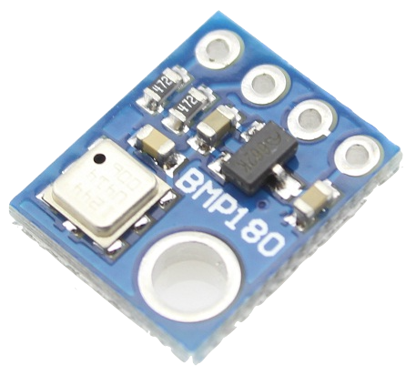
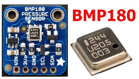
BMP180 Barometer Pressure/Temperature/Altitude Sensor
Characteristics
BMP180 Sensor Specifications
This precision sensor from Bosch is the best low-cost sensing solution for measuring barometric pressure and temperature. Because pressure changes with altitude you can also use it as an altimeter! The sensor is soldered onto a PCB with a 3.3V regulator, I2C level shifter and pull-up resistors on the I2C pins. The BMP180 is the next-generation of sensors from Bosch, and replaces the BMP085. The good news is that it is completely identical to the BMP085 in terms of firmware/software/interfacing – you can use any example code/libraries for BMP085 as a drop-in replacement.
-
Specification
- I2C interface (2 wires)
- Supply voltage 1.8V to 3.6V
- Pressure sensing range: 300-1100 hPa (9000m to -500m above sea level)
- Up to 0.03hPa / 0.25m resolution
- -40 to +85°C operational range, +-2°C temperature accuracy
Sketch compiler defines
Library enabler:
#define THERMO_BMP180 1
Type selection:
only one type
PIN definition:
Depend on the I2C board mapping (SDA and SCL)
App Variable assignment:
#define VIRTUAL_VAR_INDEX_TEMP_TMP180 8
#define VIRTUAL_VAR_INDEX_PRESS_TMP180 9
#define VIRTUAL_VAR_INDEX_ALT_TMP180 10
#define VIRTUAL_VAR_INDEX_SEAL_PRESS_TMP180 11
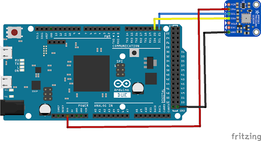
Schematic connections
Arduino PINS:
- SDA (data)
- SCL (clock)
AndruinoApp sensor:
- Add a new sensor (generic variable)
- select variable from 8 to 11 (temp, press, alt, seal presure)
How to display it on AndruinoApp
From Andruino App, select board name and variable number:
- Temperature: variable number 8
- Pressure (hP): variable number 9
- Altitude: variable number 10
- Seal pressure: variable number 1
Andruino Winner during Arduino-Day 2019
Andruino Project has been selected by a panel of experts as the winner of the HOME AUTOMATION category in the Arduino Day Community Challenge
Andrea Scavuzzo